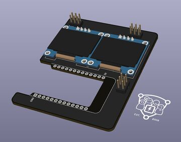
The idea for this year's Labor badge is based on the Swag Badge from the Open Hardware Miniconf at linux.conf.au 2021.
They also released a DIY version named Dag Badge as well as the Swag Badge schematics.
You can do fun things with this badge. We made a basic kit as we sell it, with optional extras.
This is in part for educational purposes, so people can try different things, e.g., discover that I2C needs different addresses or separate buses vs SPI being controlled via active low select pins. The top area has holes for prototyping, not connected to anything.
- power and system LEDs
- 2 OLED screens on I2C (top)
- 2 buttons
- double pin rows + ESP32 D1 mini board
- 2 color screens on SPI
- 2 thumb sticks with buttons and x,y axis
- 2 expansion ports with I2C and DAC-capable GPIOs (top left+right)
This is our own PCB design. We will offer a basic kit with the PCB itself, the ESP32 D1 Mini board, 2 OLED displays, and 2 push buttons, to keep it simple and inexpensive. Anyone can purchase the additional parts if they like and we may have some left over from testing, and of course, feel free to fork and rework the PCB as you like, print it yourself, file PRs, or just leave some feedback.
Size (rounded): 94mm x 130mm
See the schematics for details.
The data sheet and documentation for the ESP32-WROOM-32 is publicly available.
It includes schematics and application notes.
https://www.az-delivery.de/products/esp32-d1-mini
The ESP32 has VDET pins which can be used for ADC.
NOTE: At Labortage 2021, we sold badges with the MH-ET LIVE MiniKit, because it was a cheap option and easily available, unlike the otherwise preferred board "ESP32 D1 Mini NodeMCU". It has some quirks, but is generally fine to use.
We have bridged button B (right) to GPIO0, so you can press it for flashing or otherwise triggering the "boot option" as described in the WROOM-32 datasheet.
- forum with resources overview
- repo with sample files for Arduino
- issue: schematics not fully accurate
- issue: RX/TX in top right are swapped
Use the Makefile to clear the SPI flash and write an image to it:
make FW=firmware-image.bin erase flashYou can pass down parameters. For further options, please look at Makefile.
NOTE: One common board is the MH-ET LIVE ESP32 MiniKit. In order to flash it,
you need to short GPIO0 to GND and use the assigned /dev/ttyACM{n} device.
We have started to write our own bare firmware in Rust. 🦀
It is non-std and based on esp-rs.
It's in beta and we were having trouble getting MQTT and WiFi to work reliably.
Use ampy to upload scripts. On
many OS distributions, you can find a package for it.
The ESP32 variant is also still in beta on NodeMCU, though may do better than MicroPython. We haven't tested it too much yet, but it does boot up thus far and MQTT worked okay.
Use nodemcu-tool to upload
scripts. If you are using Arch Linux, you can use the package from the AUR. Otherwise,
use the PKGBUILD as a reference for building it; mind that you may need to
rebuild the native modules.
Follow the build instructions for full customization or use a prebuilt image from the cloud build service.
Try out a small libstyx implementation suitable for use on ESP32.
See also the more recent NinePea.
TODO: See if you can wire it up with cpu to enable speedier driver development,
e.g., using a related ESP32 board with an ethernet port, or attach
one to the badge even.
There are many suitable and colorful 6x6 buttons, tall and high, though not as nice to press. We went with the larger 12x12 retro arcade style tactile push buttons instead.
We have routed the buttons to the pins IO0 and IO2.
Note: On the back, we need to solder a bridge on one display in order to change its address, so we can use both on the same bus.
The module is based on the SSD1306. See also the data sheet and

https://www.az-delivery.de/en/products/0-96zolldisplay
PS2 joysticks and corresponding caps are available from Amazon and probably other sources as well.
The Freetronics Kicad library has a model for it.
They have two potentiometers for the two dimensions each, so we assign GPIO pins to them:
| function | left | right |
|---|---|---|
| X axis | IO33 | IO32 |
| Y axis | IO34 | IO35 |
| button | IO5 | IO12 |
https://www.mischianti.org/2020/05/30/esp32-pinout-specs-and-arduino-ide-configuration-part-1/


